Sniffing and decoding NFC with a DVB-T stick (RTL-SDR) and GNURadio
By JC on Sunday 15 October 2017, 20:55 - Hacking - Permalink
Several months ago, we got a new coffee dispenser machine at work that waits for an NFC tag before pouring a hot beverage. Everyone has a tag, and with this tag, we get free drinks. At first I wanted to clone it, so I played with this nice and inexpensive NFC reader (based on the well supported PN532 chip), but found out my tag, which is a Mifare Classic 1K from NXP (MF1 IC S50), was not vulnerable anymore to the current available cloning technique. Since I had never played with NFC before, I still wanted to get some data and see what I could do with it. So I switched to a new goal which was sniffing an NFC transaction between the coffee dispenser machine and my tag.
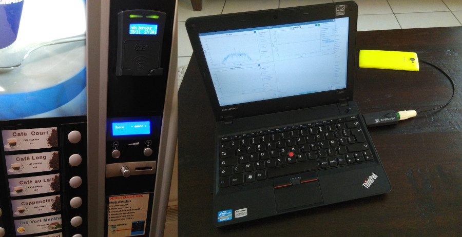
Googling around, I quickly found the easiest way to do that was to get something like the Proxmark3 board, but getting free drink from a machine that already delivers free drinks failed to convince me to buy this expensive tool. I then remembered I got an RTL-SDR compatible DVB-T dongle, and started looking for a piece of software that would demodulate and decode NFC. Unfortunately I found none, so I decided to try to do it myself.
How NFC works
Let's first look at how NFC works. NFC uses a carrier frequency of 13,56 MHz, and provides three bit-rates within the 14kHz allowed bandwidth which are 106 kbps, 212 kbps, and 424 kbps. The communication involves either an active device and a passive device (for instance, a smartphone and an NFC tag), or two active devices (two smartphones for instance). In both cases, the first device is the initiator, and the other one is the target. Depending on the type of NFC, the modulation used, the line code on top of it, and the allowed bit-rates are not the same.
For the initiator to target communication:
- NFC Type A -> 100% ASK (also called OOK), 106 kbps, modified Miller code LSB first
- NFC Type B -> 10% ASK, 106 kbps, NRZ-L code LSB first
- NFC Type F -> 10% ASK, 212 kbps and 424 kbps, Manchester code MSB first
For the target to initiator communication (modulation of a 847 kHz subcarrier):
- NFC Type A -> 100% ASK (also called OOK) , 106 kbps, Manchester code LSB first
- NFC Type B -> BPSK, 106 kbps, NRZ-L code LSB first
- NFC Type F -> 10% ASK, 212 kbps and 424 kbps, Manchester code MSB first
The cool thing with NFC is that a passive device does not need its own power source to be able to respond. Instead, it is powered by the electromagnetic field generated by the initiator when it sends data to the target. My tag being an NFC Type A device, let's look at the line codes used for this type.
The modified Miller coder sends 4 symbols to the modulation layer per bit coded. So instead of sending a 0 to code a 0, and a 1 to code a 1, it sends:
- 0111 to code a 0 if the previous bit was 0 or a Start
- 1111 to code a 0 if the previous bit was 1
- 1101 to code a 1
The START of the frame is indicated by a logical 0, and its END by a logical 0 followed by a 1111 sequence.

The actual bit-rate is the modulation bit-rate divided by 4.
The Manchester code is simpler. It codes a bit using the two possible symbol transitions:
- 0 -> 01 (Low/High)
- 1 -> 10 (High/Low)
The START of the frame is indicated by a logical 1, and its END by a 11 sequence. When the signal is High, the carrier is modulated by the subcarrier.
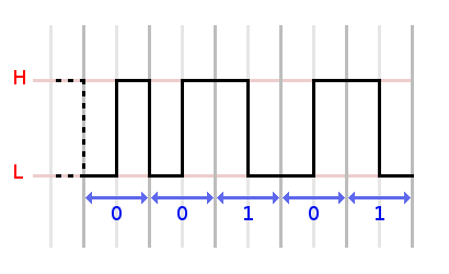
The actual bit-rate is the modulation bit-rate divided by 2.
RTL-SDR and 13,56 MHz
Now that we know how NFC works, let's see if we can demodulate it. First issue was the 13,56 MHz. My DVB-T dongle is based on the Rafael Micro R820T tuner, and has a range of 24 MHz - 1766 MHz, and anyway, most DVB-T dongles start at around 20 MHz. I found two solutions to this. The first one is to tune the DVB-T dongle to the most powerful harmonic, and hope there is enough power to demodulate the signal. The second and third harmonics, respectively 27,12 MHz and 40,68 MHz for NFC, are often good choices, but they might show some annoying distortions. Since we really are in near field (like dongle antenna between the tag and machine near), there was a good chance it would work (and it did !). The second solution is this heavily modified rtl-sdr driver that allows the DVB-T dongle to go down to 13,56 MHz by disabling the tuner's PLL, thus allowing the RTL2832U chip to get some of the signal unchanged, and adjust its intermediate frequency accordingly. What happens exactly to the tuner depends on the range selected, and is well explained on the GitHub web page. Since the last commit on this fork was few years old, I created my own rtl-sdr fork that I try to keep in sync with the upstream drivers here and here.
Even if I actually started to demodulate NFC using the first solution, I still wanted to test the patch since it is always better to tune at the right frequency, and it worked great for my needs. However, it looks like the results vary a lot from dongle to dongle, so try both solutions, and pick the one that works best for you.
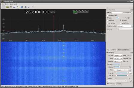
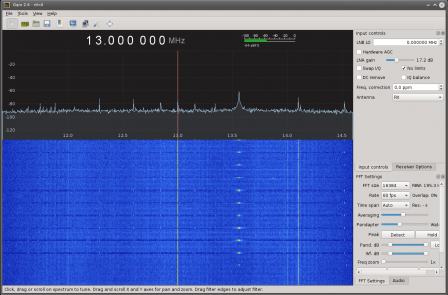
Here is the "NFC ping" of a smartphone viewed with Gqrx, using both solutions:
If you want to use the modified rtl-sdr driver with GNURadio and Gqrx on Ubuntu 14.04 - 16.04, without rebuilding everything yourself :
- Remove any source or binary of previous versions:
$ sudo apt-get purge --auto-remove gqrx
$ sudo apt-get purge --auto-remove gqrx-sdr
$ sudo apt-get purge --auto-remove gnuradio
$ sudo apt-get purge --auto-remove libgnuradio*
$ sudo apt-get purge --auto-remove libuhd003
- Add all the needed PPAs to get the latest relevant packages:
$ sudo add-apt-repository -y ppa:bladerf/bladerf (for 14.04 - 15.10 only)
$ sudo add-apt-repository -y ppa:ettusresearch/uhd
$ sudo add-apt-repository -y ppa:myriadrf/drivers
$ sudo add-apt-repository -y ppa:myriadrf/gnuradio
$ sudo add-apt-repository -y ppa:gqrx/gqrx-sdr
$ sudo apt-get update
- Install the latest libs and tools:
$ sudo apt-get install gqrx-sdr gnuradio
- Clone the modified rtl-sdr git, build it, and install it:
$ git clone https://github.com/jcrona/rtl-sdr.git
$ mkdir rtl-sdr/build
$ cd rtl-sdr/build
$ cmake ../
$ make
$ sudo make install
- Refresh ld cache:
$ sudo ldconfig
Now you can start Gqrx, select the RTL dongle, check the No limits checkbox, and verify you can go down to 13,56 MHz.
If you want to be sure that the modified rtl-sdr driver is in use, run:
$ ldd /usr/bin/gqrx | grep librtlsdr
You should see:
librtlsdr.so.0 => /usr/local/lib/librtlsdr.so.0 (0x00007ffb16445000)
The local folder indicates you are using the version you just built.
If you want to go back to the official rtl-sdr driver:
$ cd rtl-sdr/build
$ sudo make uninstall
$ sudo ldconfig
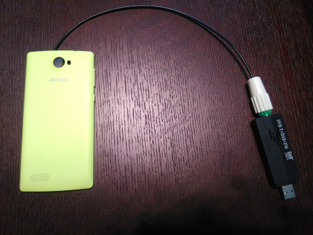
Now regarding the antenna, I used a smartphone cover I had laying around, and connected it to the dongle without any kind of matching. This is not ideal, but worked well enough for me.
Demodulation
To demodulate an NFC transaction, we need to demodulate two different signals. The first one corresponds to the initiator to target communication (the coffee dispenser machine queries to the tag), while the second one corresponds to the target to initiator communication (the tag responses to the coffee dispenser machine). The tag was an NXP Mifare Classic 1K (NCF Type A). So I knew that the machine to tag communication was OOK + modified Miller code on the 13,56 MHz carrier, while the responses were OOK + Manchester code on the 847 kHz subcarrier.
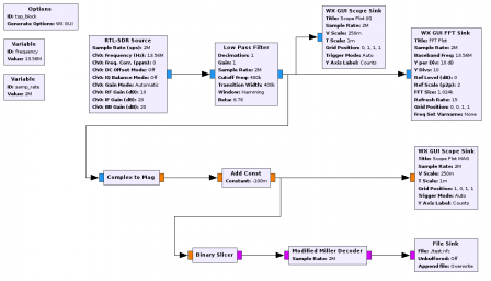
To demodulate the signal, I used the well known GNURadio Companion utility. Let's see how the demodulation is performed step by step (the resulting NFC.grc flow-graph is provided in the attachment section).
OOK
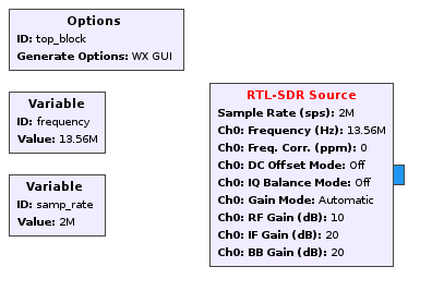
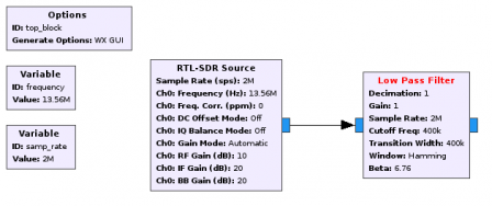
The first thing to do is to create a sample_rate Variable block (if not already there) that will be used across the chart. Let's set it to 2MHz which is enough. Let's also configure the Option block to WX GUI right away. Then we start the chart with an RTL-SDR Source block tuned to the right frequency. Let's also create a frequency Variable block for this. It is 13,56 MHz if you use the modified rtl-srd driver, 27,12 MHz for the second harmonic, or 40,68 MHz for the third harmonic.
To narrow down the signal to the bandwidth we want, we need to add a Low Pass Filter block. The expected bandwidth is 14 kHz, but the sidebands extend up to +-1.8 MHz. After a lot of testing, I found that a Hamming window with a cutoff frequency and a transition width of 400 kHz works well to get enough information to demodulate the signal without getting too much noise.
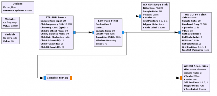
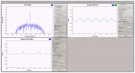
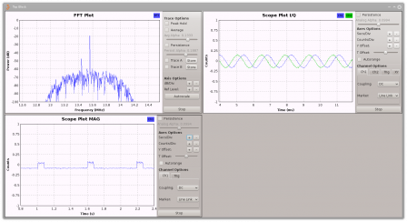
At that point, we can plot the FFT (WX GUI FFT Sink block) and the signal (WX GUI Scope Sink block) to see if everything looks OK.
Now, to see the real signal, we need to get the magnitudes of the I/Q samples. This will give the envelope of the waveform which should be a rectangular signal for OOK. To do this we use the Complex to Mag block. We can also add a new WX GUI Scope Sink block to see the result.
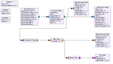
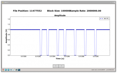
The result looks great, but there is too much information compared to what we want. We only need a 1 bit output saying 0 or 1. To do that we can use the Binary Slicer block, but the signal needs to cross the 0 axis. The solution is to add an Add Const block to shift the signal down a little bit for the binary slicer. An offset of -0,1 or -0,15 was enough for me, but it depends on the amplitude of your signal. Then we can add a File Sink block to save the output in a file that can be plotted using the grplotchar command.
Looking at the raw output, we can see the "ping" preformed by the smartphone.
Now, what remains is to decode the modifier Miller code, but unfortunately, there is no provided block to do so.
Decoding the modified Miller code
Something great about GNURadio is the ability to add custom blocks, and that's exactly what I had to do to decode the modifier Miller code. The source code of the block, called Modified Miller Decoder, is provided on my GitHub. It works by counting the zeros and ones provided by the Binary Slicer block in order to measure the duration of the gaps (1) between the constant short pauses (0). It uses this equivalent table to compute the output:
- Short gap --> 0 or a Start if the previous bit was 0, a Start, or nothing
- Short gap --> 1 if the previous bit was 1
- Medium gap --> 1 if the previous bit was 0 or a Start
- Medium gap --> 00 if the previous bit was 1
- Long gap --> 01 (the previous bit is always 1)
When a gap is converted, the resulting bits include the bit to which the short pause following the gap (that triggered the conversion) belongs.

The block output is the actual data sent by the machine in binary form, but what really matters is the console output as we will see later.
In order to use this block we must first build it and install it. You first need to make sure you have SWIG installed. For Ubuntu, you just need to do:
$ sudo apt-get install swig
Then you can build and install the NFC module:
$ git clone https://github.com/jcrona/gr-nfc.git
$ mkdir gr-nfc/build
$ cd gr-nfc/build
$ cmake ../
$ make
$ sudo make install
$ sudo ldconfig
Now the Modified Miller Decoder block should be available in the GNURadio Companion interface (you need to hit the Reload Blocks button if GNURadio Companion is already running). We just need to add it between the Binary Slicer block and the File Sink block.
The only thing remaining is to hit the Run button and look at the result !
First attempt
Testing again with my smartphone, I got on the console:
linux; GNU C++ version 5.4.0 20160609; Boost105800; UHD003.010.002.000-release
gr-osmosdr v0.1.x-xxx-xunknown (0.1.5git) gnuradio 3.7.10
built-in source types: file osmosdr fcd rtl rtl_tcp uhd plutosdr miri hackrf bladerf rfspace airspy soapy redpitaya
Using device #0 Realtek RTL2838UHIDIR SN: 00000001
Found Rafael Micro R820T tuner
Exact sample rate is: 2000000.052982 Hz
[r82xx] Updated PLL limits to 26900000 .. 1885000000 Hz
Reader -> 26
Reader -> 26
Reader -> 26
Reader -> 26
Reader -> 26
Reader -> 26
>>> Done
We can see that we are now able to decode the "ping" performed by the smartphone ! Indeed, 0x26 is the REQA command which is used to probe for targets in range.
At that point, I put the antenna against the coffee dispenser machine, and looked at the output of GNURadio while I was approaching the tag. This is a part of what I got on the console:
Reader -> 50 00 57 CD
Reader -> 50 00 57 CD
Reader -> 50 00 57 CD
Reader -> 50 00 57 CD
Reader -> D3 41
Reader -> 93 E1 2C 13 8C EF 9B 1B 31 DD
Reader -> 61 50 9E 79
Reader -> 4F C7 DA 6E A8 79 9B DF 02
Reader -> D3 65 54 DD
Reader -> BC AE F6 EB
Reader -> 50 00 57 CD
Well, looking at the data, it was not at all what I was expecting. I was supposed to get a REQA (0x26) or WUPA (0x52) command, followed by the anti-collision procedure (several SELECT (0x93/0x95/0x97) commands, with some containing parts of the tag UID), but instead I had some unknown bytes, and the frames were not even aligned on 8 bits ! One good thing was the 50 00 57 CD frame, which was a regular HALT command (0x50 0x00) followed by the right CRC (0x57 0xCD).
But still, something was missing, and it was the frame format !
Frame format
Hopefully I found online a document (final draft of the ISO 14443-3 standard) explaining how the data was formatted inside an NFC frame. Basically, there are two types of frames:
- the Short frame: 7 bits, only for the REQA or WUPA commands ==> S |b0|b1|b2|b3|b4|b5|b6| E
- the Standard frame: n x (8 bits + 1 bit of odd parity) ==> S |b0|b1|b2|b3|b4|b5|b6|b7| P |b8|b9|b10|b11|b12|b13|b14|b15| P | ... | E
With that in mind, I tweaked the code of the block. The Short commands were now printed with "[]" around, the bytes followed by a wrong parity bit with "()" around, the broken bytes (less than 8 bits) with "/\" around, and the remaining bytes without anything else. I had the idea to keep the acquired raw data from the previous attempt, so I was able to easily replay them again and again in order to debug my block, and the result was clearly better:
Reader -> [52]
Reader -> [52]
Reader -> (50) (80) 55 /19\
Reader -> [52]
Reader -> [52]
Reader -> (50) (80) 55 /19\
Reader -> [52]
Reader -> 93 20
Reader -> 93 70 CB 82 F8 DF 6E 62 DD
Reader -> 61 28 67 CF
Reader -> 41 63 (B6) (0D) 9A (DB) 7E (05)
Reader -> (D3) 32 55 1B
Reader -> BC (57) FD (FD)
Reader -> (50) (80) 55 /19\
I was able to see the expected WUPA command, followed by the anti-collision procedure (SELECT commands) ! Victory ? Almost, because the only thing that looked good in the previous test did not anymore. Looking at the raw data, there was no doubt, the HALT frame was missing the parity bits on purpose. It was not a bug from neither my setup, nor my GNURadio block.
Although the standard states that the HALT command must respect the Standard frame format, I assumed that removing the parity bits was somehow allowed in some cases.
So I modified the algorithm in the block one last time, allowing it to properly display frames that look good without parity bits (length multiple of 8 bits), but do not with parity bits (length not multiple of 9 bits). The remaining frames that have a length multiple of 9 x 8 = 72 bits are displayed according to the parity mode of the previous frame.
Final result
Here is the final result I got:
linux; GNU C++ version 5.4.0 20160609; Boost105800; UHD003.010.002.000-release
gr-osmosdr v0.1.x-xxx-xunknown (0.1.5git) gnuradio 3.7.10
built-in source types: file osmosdr fcd rtl rtl_tcp uhd plutosdr miri hackrf bladerf rfspace airspy soapy redpitaya
Using device #0 Realtek RTL2838UHIDIR SN: 00000001
Found Rafael Micro R820T tuner
Exact sample rate is: 2000000.052982 Hz
[r82xx] Updated PLL limits to 26900000 .. 1885000000 Hz
Reader -> [52]
Reader -> [52]
Reader -> 50 00 57 CD (No parity)
Reader -> [52]
Reader -> [52]
Reader -> 50 00 57 CD (No parity)
Reader -> [52]
Reader -> [52]
Reader -> 50 00 57 CD (No parity)
Reader -> [52]
Reader -> [52]
Reader -> 50 00 57 CD (No parity)
Reader -> [52]
Reader -> [52]
Reader -> 50 00 57 CD (No parity)
Reader -> [52]
Reader -> [52]
Reader -> 50 00 57 CD (No parity)
Reader -> [52]
Reader -> [52]
Reader -> 50 00 57 CD (No parity)
Reader -> [52]
Reader -> [52]
Reader -> 50 00 57 CD (No parity)
Reader -> [52]
Reader -> [52]
Reader -> 50 00 57 CD (No parity)
Reader -> [52]
Reader -> 93 20
Reader -> 93 70 CB 82 F8 DF 6E 62 DD
Reader -> 61 28 67 CF
Reader -> 41 63 (B6) (0D) 9A (DB) 7E (05)
Reader -> (D3) 32 55 1B
Reader -> BC (57) FD (FD)
Reader -> 50 00 57 CD (No parity)
Reader -> [52]
Reader -> 93 20
Reader -> 93 70 CB 82 F8 DF 6E 62 DD
Reader -> 61 2C 43 89
Reader -> (CF) (51) (04) 5C (CA) (83) 15 (F8)
Reader -> (52) (0C) (32) 1B
Reader -> (82) 17 (6B) (BB)
Reader -> 50 00 57 CD (No parity)
Reader -> [52]
Reader -> 93 20
Reader -> 93 70 CB 82 F8 DF 6E 62 DD
Reader -> 61 2C 43 89
Reader -> (FE) F5 E4 (23) (BB) 7E (CB) 52
Reader -> FE 9F (A7) (CD)
Reader -> 0B (4C) 4B 03
Reader -> 50 00 57 CD (No parity)
Reader -> [52]
Reader -> [52]
Reader -> 50 00 57 CD (No parity)
Reader -> [52]
Reader -> [52]
Reader -> 50 00 57 CD (No parity)
>>> Done
Let's analyze a small part of it:
Reader -> [52] ==> REQA
Reader -> [52] ==> REQA
The reader sends REQA commands to probe the field for tags.
Reader -> 50 00 57 CD (No parity) ==> HALT
The reader sends a HALT command to deactivate any tag in the field (the CRC 57 00 is OK). The REQA and HALT commands are sent in loop while there is no tag in the field.
Reader -> [52] ==> REQA
The reader sends a new REQA command, but this time the tag is in the field. It is supposed to respond with an ATQA.
Reader -> 93 20 ==> SELECT Cascade 1 (no UID provided)
The reader detected a tag, and launches the anti-collision procedure by sending a SELECT Cascade 1 command without any bit of UID. All tags in the field are expected to respond with their respective UIDs.
Reader -> 93 70 CB 82 F8 DF 6E 62 DD ==> SELECT Cascade 1 (UID provided)
The reader received the tag UID, and activates this particular tag by sending a new SELECT command, along with the UID targeted (the CRC 62 DD is OK). The tag is expected to respond with a SAK command, indicating the type of the tag and if the anti-collision procedure is complete (no more UID byte available to transmit).
Reader -> 61 28 67 CF ==> AUTH
The reader sends an authentication request (AUTH) in order to start the ciphering procedure (the CRC 67 CF is OK). The tag is expected to respond with a nonce (nT). From this point, all data will be encrypted.
Reader -> 41 63 (B6) (0D) 9A (DB) 7E (05) ==> Encrypted data
The reader sends a nonce (nR) and its response (aR) to the tag. The tag is expected to answer with its response (aT). From this point the authentication procedure is finished.
Reader -> (D3) 32 55 1B ==> Encrypted data
Reader -> BC (57) FD (FD) ==> Encrypted data
The reader now sends Mifare commands, probably READ commands. The tag is expected to respond with the data stored in it.
Reader -> 50 00 57 CD (No parity) ==> HALT
The reader sends a HALT command to deactivate the tag.
Everything looked OK ! I was able to demodulate the coffee dispenser machine to tag communication just fine with my DVB-T dongle !
What's next
Obviously, this is just one half of the whole communication. I still need to demodulate the tag response to the machine. I'll add any needed custom block to the gr-nfc Git so that everything will be in the NFC package.
So, to be continued ...
